|
THE BITURBO ENGINE V-6 CYLINDER 18-VALVES |
 |
|
| NOTICE: THERE ARE MANY IMAGES ON THIS PAGE SO PLEASE BE PATIENT!!! | ||
Once again I must thank Dott. Matteo Panini for allowing me to photograph the V-6 Merak engine and the V-6 18-valve Biturbo engine that form part of his wonderful collection. We are indeed fortunate that such an important Maserati collection has fallen into the hands of such a passionate and unselfish enthusiast. |
||||||||||||||
Derived in principle from the chain driven four overhead camshaft 1999 cc V-6 engine that powered the Merak 2000, this 1996 cc engine differed from that design in that it evolved into a cambelt driven twin overhead camshaft V-6 engine with three valves per cylinder, two intake valves of differing diameter to provide a swirl effect, said to increase combustion efficiency and thereby preformance, and a single large diameter exhaust valve. Bore and stroke sizes varied from 80mm x 66.3mm for the Merak engine to 82mm x 63.5mm for the Biturbo engine.  INTAKE EXHAUST This compact all alloy engine, with wet 'Nigusil®' treated cylinder liners, during early tests produced a power output of around 150 bhp when normally aspirated. De Tomaso wanted more for his new Biturbo coupe, so the engine was fitted with two small IHI turbochargers (built by Ishikawajima-Harima Heavy Industries Co. of Japan), one per bank of cylinders. The power increase was dramatic, and utilising a single twin-choke Weber carburettor power was increased to a healthy 180 bhp at 6000 rpm.  THE EARLY BITURBO ENGINE FITTED WITH A SINGLE TWIN-CHOKE WEBER CARBURETTOR Note: The traditional turbocharging system where the wastegate is opened by direct pressure from the compressor to the diaphragm valve.
Not many owners realised that these early models had no rev-limiter and contained a 'black box' that indicated when the driver had exceeded the recommended rev limits. If owners were found to have exceeded these limits their warranty was invalidated!  NOTE HOW ONE CAM LOBE OPERATE THE TWO INTAKE VALVES The engine was then fitted with an MABC®, the Maserati Automatic Boost Control system. This system ironed out many of the problems of the earlier engine by continuous monitoring of the turbocharger's boost pressure. It was impossible to over-boost as the opening of the wastegates was dependent on the boost pressure and not the needs of the engine.  THE MASERATI AUTOMATIC BOOST CONTROL SYSTEM
Development continued and in 1983 the Biturbo S was launched for the home market, twin air-to-air intercoolers, water-cooled turbos and a new MABC management system were added and power was increased to 205 bhp at 6500 rpm.  NOTE THE TWIN AIR-TO-AIR INTERCOOLERS OF THE BITURBO S In 1983 a 2.5-litre engine (2491 cc) was added to the range, primarily for the foreign market. This engine produced between 188 bhp in the Biturbo 2500 to 200 bhp in the 425. This engine was uprated in 1984 with the introduction of the Biturbo ES with power output increased to 205 bhp at 6500 rpm.  THE WEBER-MARELLI INTEGRATED ELECTRONIC FUEL INJECTION AND IGNITION SYSTEM In an effort to improve the reliability and versitility of the engine, Maserati introduced the Biturbo i in 1986. This model was fitted with a Magneti/Marelli electronic fuel injection and ignition systems along with twin air-to-air intercoolers increased its power output to 188 bhp at 6000 rpm. Later that year an sportier version, the Biturbo Si, appeared with power increased to 220 bhp at 6350 rpm.   THE 220 BHP ENGINE AND MANAGEMENT SYSTEM OF THE BITURBO Si 1987 also saw the introduction of a luxury coupé, the 228i, this model, primarily designed for the export market, was fitted with a 2.8-litre engine (2790cc) producing 250 bhp at 6000 rpm. Between 1987 and its demise in 1994, this engine was fitted to the Spyder iE, the 430, the 222, the 422, the Spyder iE 90, the 4.18v., the 222 SE, the 222 SR and the Karif. Throughout the 2.8-litre model range, power output varied from 225 bhp to 250 bhp depending on whether the car was fitted with a catalytic converter. The noteable exception was the Karif (without cat.) which in early literature was quoted at producing a stomping 285 bhp at 6000 rpm. Many believe the true figure to be nearer 250!! |
||||||||||||||
YELLOW - illustrates the passage of oil in the lubrication system. |
||||||||||||||
PALE BLUE - illustrates the passage of water in the cooling system. |
||||||||||||||
WHITE - illustrates the passage of the forced cool air in the induction system. |
||||||||||||||
GREEN - illustrates the passage of the fuel/air in the induction system. |
||||||||||||||
ORANGE - illustrates the passage of the hot exhaust gases. |
||||||||||||||
| YOU WILL NOTE THAT THIS ENGINE DOES NOT ILLUSTRATE THE TWO INTERCOOLERS. | ||||
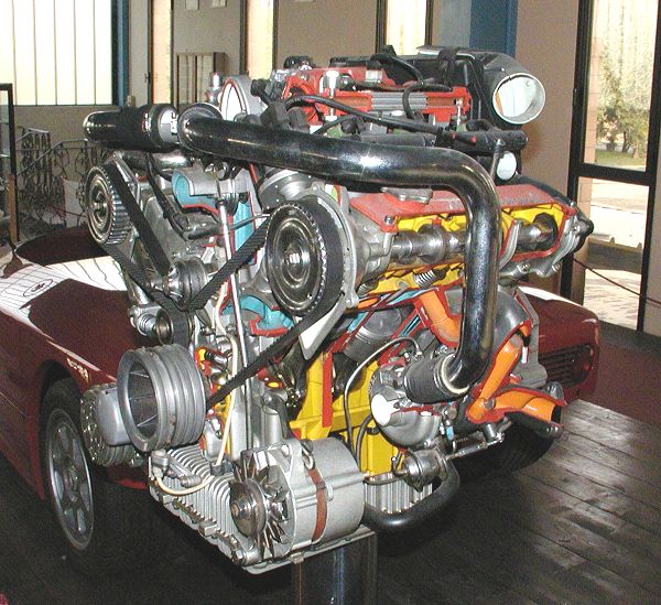 The V-6 @ 90° 18-valve Biturbo i engine |
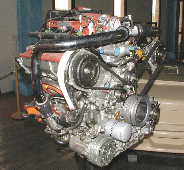 The V-6 @ 90° 18-valve Biturbo i engine |
|||
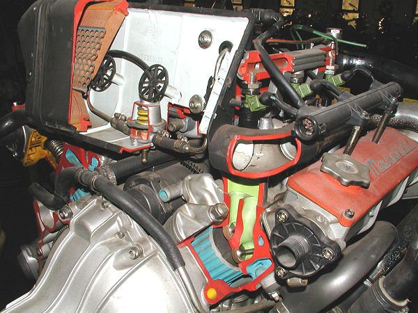 The fuel pressure regulator located behind the air filter |
 Forced air from the two turbos enters the throttle body via this collector |
|||
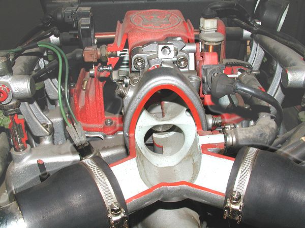
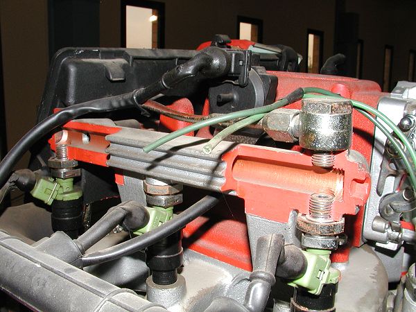 The fuel supply rail with injectors |
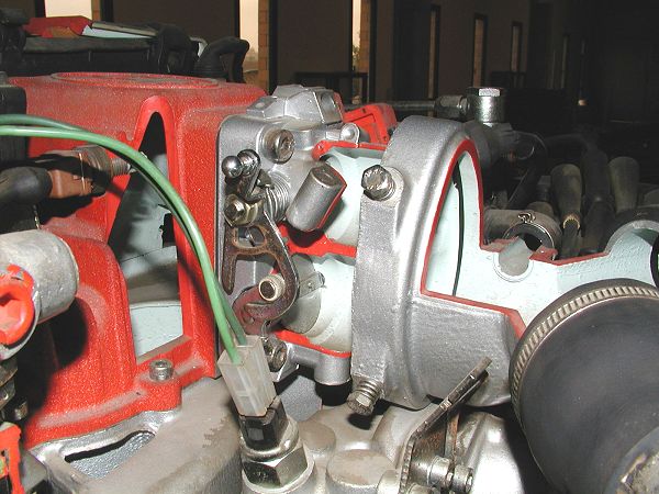 The plenum chamber and throttle body |
|||
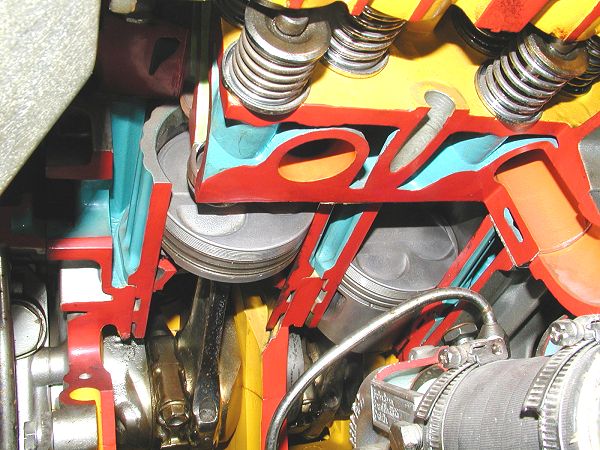
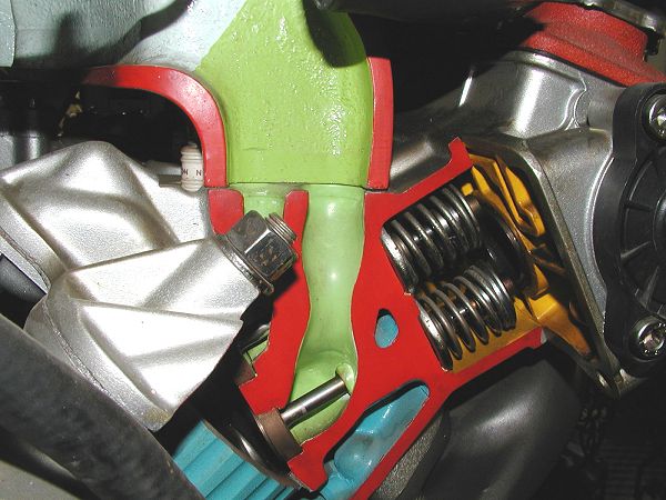 The two small intake valves per cylinder |
 The single large exhaust valve per cylinder |
|||
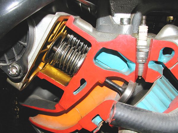
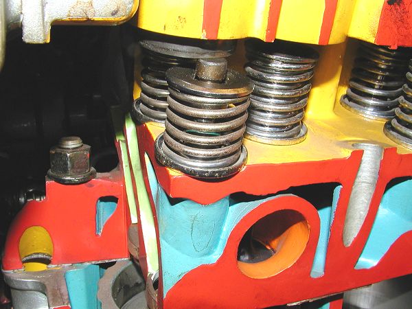 The valve stems and valve springs for the intake and exhaust valves |
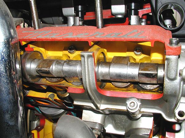 The camshaft: Two lobes per cylinder, note how one cam lobe operates the two intake valves, the other the single exhaust valve. |
|||
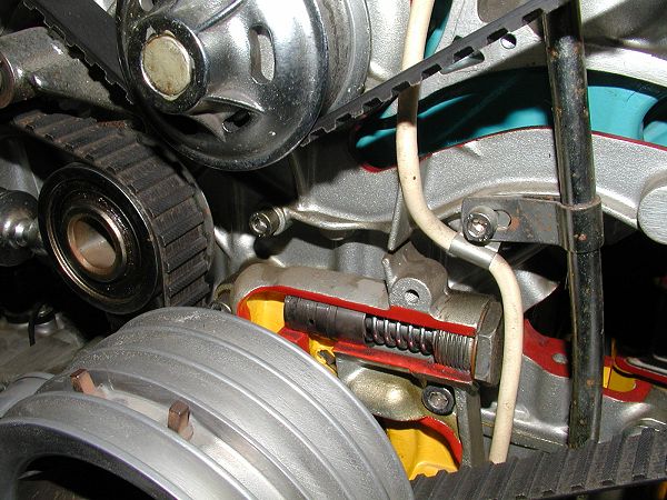
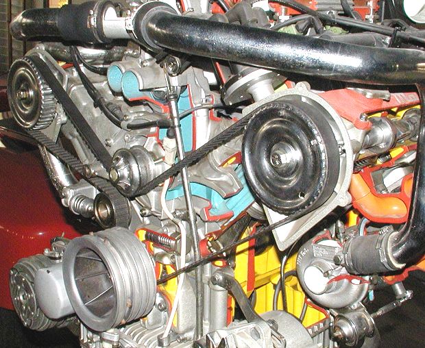 The oil level dipstick that should be checked every week and the timing belt that should be replaced every 25,000 miles or every two years!!! |
||||
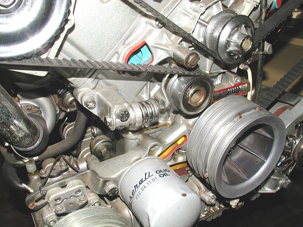 The adjustable timing belt tensioner, oil filter and crankshaft pulley |
 The oil pump pressure adjusting valve |
|||
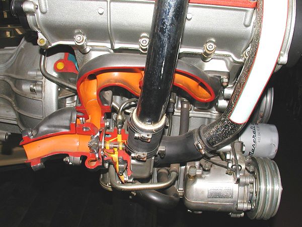 A turbocharger and the air-con compressor - note the oil passages through the IHI turbochargers |
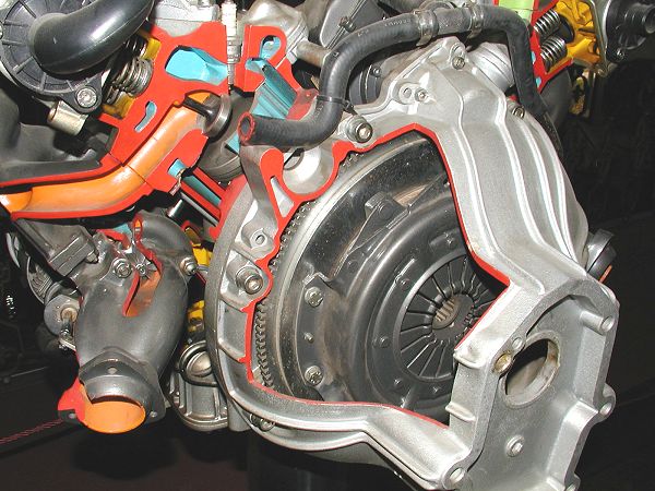 Bell-housing showing flywheel, clutch and pressure plate |
|||
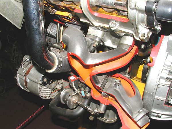 The alternator, exhaust manifold and turbo waste gate |
 The piston, con-rod and cylinder liner |
|||
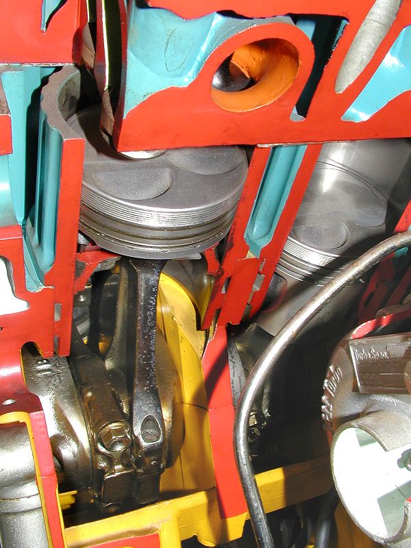 Two of the three pistons per bank, note the wet cylinder liners |
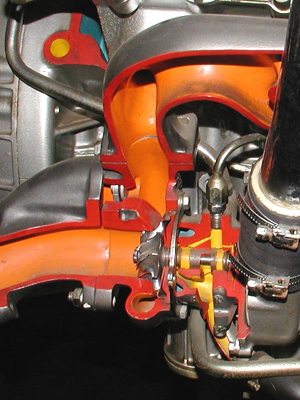 Turbocharger: Note the exhaust driven impeller |
|||
 |
||
|
To enter Enrico's Maserati Pages CLICK HERE! Copyright: Enrico's Maserati Pages - © 2003-2004. All rights reserved. |