| Maserati Ghibli II Schematic Electrical Wiring Diagrams |
||
| 2.0 and 2.8-litre Production (1992-1998) UPDATED: 21-08-2009 |
||
 |
|||||
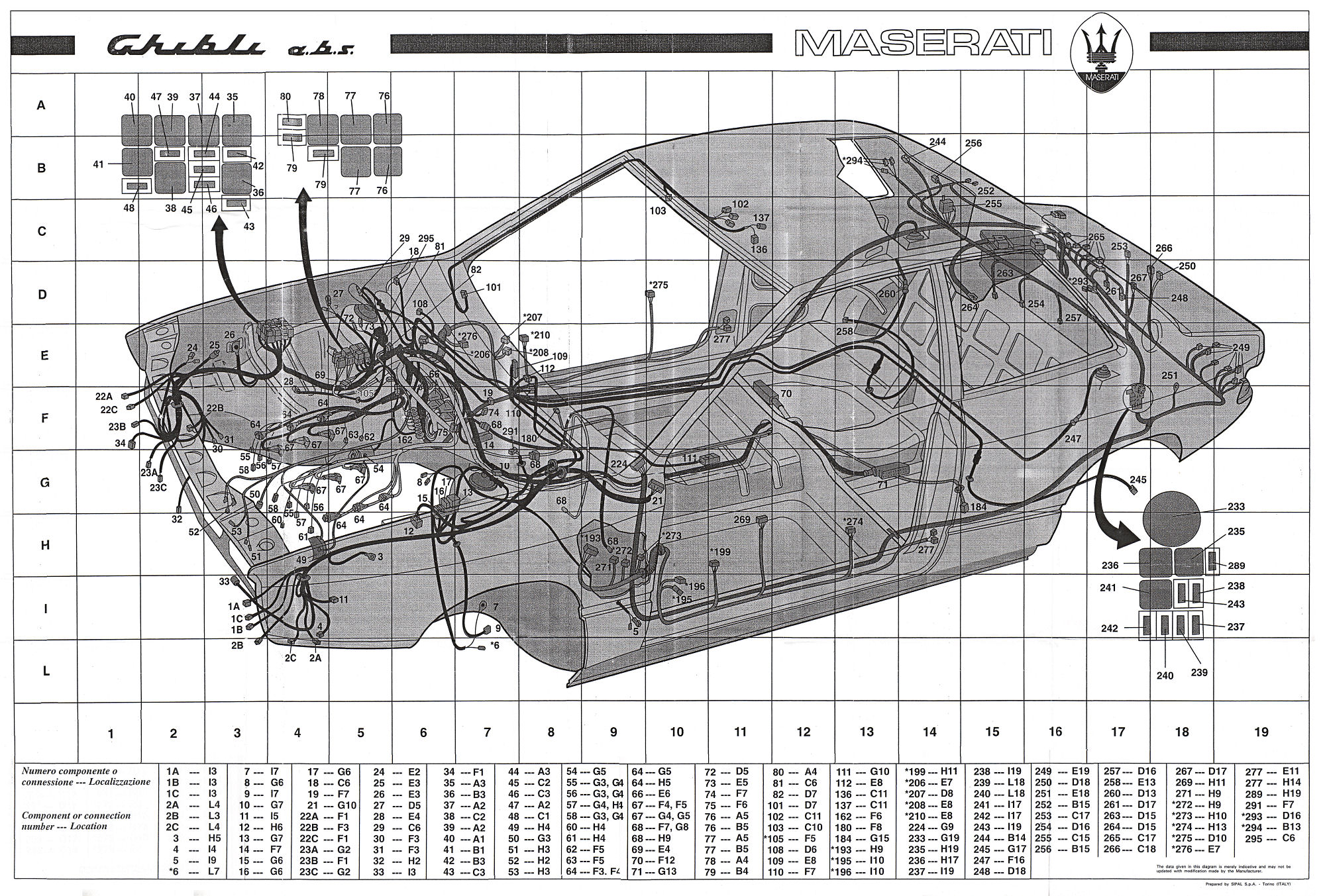
| Index to schematic electrical diagram | |||||
| Number | Component | Location | Number | Component | Location |
| 01 | Front left headlamp | 36 | Relay for 2nd engine cooling fan (in engine bay fuse box) | B 3 | |
| A | Dipped headlight | I 3 | 37 | Relay for main beam headlight control (in engine bay fuse box) | A 2 |
| B | Main beam headlight | I 3 | 38 | Relay for dipped headlight control (in engine bay fuse box) | C 2 |
| C | Headlight alignment corrector motor | I 3 | 39 | Relay for foglights control (in engine bay fusebox) | A 2 |
| 02 | Front left lamps unit | 40 | Relay for air conditioner compressor control (in engine bay fusebox) | A 1 | |
| A | Direction indicator | L 3 | 41 | Start enable relay (in engine bay fuse box) | B 1 |
| B | Side light | L 4 | 42 | Fuse protecting Ist engine cooling fan (in engine bay fusebox) | B 3 |
| C | Foglight | L 3 | 43 | Fuse protecting 2nd engine cooling fan (in engine bay fusebox) | C 3 |
| 03 | Front left ground/earth | H 5 | 44 | Fuse protecting main beam headlights (in engine bay fusebox) | A 3 |
| 04 | Wiring for headlight washer electric pump | I 4 | 45 | Fuse protecting dipped headlights (in engine bay fusebox) | C 2 |
| 05 | Front left repeater indicator | I 9 | 46 | Fuse protecting main beam headlights and headlight alignment corrector (in engine bay fusebox) | C 3 |
| *06 | Front left brake pad wear sensor | L 7 | 47 | Fuse protecting foglights (in engine bay fusebox) | A 2 |
| 07 | Ground out shock absorber | I 7 | 48 | Fuse protecting air conditioner compressor (in engine bay fusebox) | C 1 |
| 08 | Brake fluid low level sensor | G 6 | 49 | Alternator | H 4 |
| 09 | Sensor on front left wheel (ABS) | I 7 | 50 | Engine oil low level sensor | G 3 |
| 10 | Motor for front left automatic suspension control system | G 7 | 51 | Engine oil pressure sender and low engine oil pressure signalling switch | H 3 |
| 11 |
Window washer electric pump |
I 5 | 52 | Engine coolant temperature sender and thermometric switch for high temperature indicator | H 2 |
| 12 | Electro-hydraulic control unit for wheel antilock system (ABS) | H 6 | 53 | Air conditioner compressor | H 3 |
| 13 | Relay for wheel antilock system (ABS) | G 7 | 54 | Starter motor | G 5 |
| 14 | Electronic control unit for wheel antilock system (ABS) | F 7 | 55 | RPM sensor | G 3, G 4 |
| 15 | 10A fuse protecting wheel antilock system (ABS) | G 6 | 56 | Phase sensor | G 3, G 4 |
| 16 | 25A fuse protecting wheel antilock system (ABS) | G 6 | 57 | Electronic injection engine coolant temperature sensor | G 4, H 1 |
| 17 | 50A fuse protecting wheel antilock system (ABS) | G 6 | 58 | Knock sensor | G 3, G 4 |
| 18 | Connection between dashboard cable & wheel antilock system cable (ABS) | C 6 | 59 | Overboost solenoid valve | Not shown |
| 19 | Diagnostic socket for wheel antilock system (ABS) | F 7 | 60 | Potentiometer on throttle valve | H 4 |
| 20 | Windscreen wiper control assembly | 61 | Auxiliary air solenoid valve | H 4 | |
| 21 | Connection between dashboard cable and left engine bay cable | G 10 | 62 | Air temperature sensor | F 5 |
| 22 | Front right headlamp | 63 | Absolute pressure sensor | F 5 | |
| A | Dipped headlight | F 1 | 64 | Ignition coil | F 3, F 4 |
| B | Main beam headlight | F 3 | 65 | Spark plug | Not shown |
| C | Headlight alignment corrector motor | F 1 | 66 | Electronic ignition module | E 6 |
| 23 | Front right lamp units | 67 | Injector | F 4 & 5, G 4 & 5 | |
| A | Direction indicator | G 2 | 68 | Heated Lambda sensor | F 7, G 8 & H 9 |
| B | Side light | F 1 | 69 | Interconnection between two banks of cylinders in injection system | E 4 |
| C | Foglight | G 2 | 70 | Electronic injection control unit controlling cylinders 1,2,3 | F 12 |
| 24 | Electrical horn | E 2 | 71 | Electronic injection control unit controlling cylinders 4,5,6 | G 13 |
| 25 | Electric vacuum pump | E 3 | 72 | Electronic injection connector for cylinders 1,2,3 | D 5 |
| 26 | Front right ground/earth | E 3 | 73 | Electronic injection connector for cylinders 4,5,6 | E 5 |
| 27 | Dipped headlight | D 5 | 74 | Diagnostic socket for injection system - cylinders 1,2,3 | F 7 |
| 28 | Sensor on front right wheel (ABS) | E 4 | 75 | Diagnostic socket for injection system - cylinders 4,5,6 | F 6 |
| 29 | Motor for front right automatic suspension control system | C 6 | 76 | Relay controlling injectors and electronic injection control unit in injection system relays/fusebox | A 5, B 5 |
| 30 | First engine cooling fan | F 3 | 77 | Relay supplying ignition coil (in injection system relays/fusebox) | A 5, B 5 |
| 31 | Second engine cooling fan | F 3 | 78 | Relay controlling electric fuel pump and heated Lambda sensor On injector system relays/fusebox) | A 4 |
| 32 | Engine radiator cooling fan thermostatic switch | H 2 | 79 | 30A fuse protecting electronic injection system (in injection system relays/fusebox) | B 4 |
| 33 | External temperature sensor | I 3 | 80 | 30A fuse for heated Lambda sensor & electric fuel pump relay (in injector system relay/fusebox) | A 4 |
| 34 | 3-level pressure switch | F 1 | 81 | Connection between dashboard cable and engine bay cable (7-way connector) | C 6 |
| 35 | Relay for 1st engine cooling fan (in engine bay fuse box) | A 3 | 82 | Connection between dashboard cable and engine bay cable (10-way connector) | D 7 |
| 101 | Connection between dashboard and ceiling lamp cable | D 7 | 242 | 15A fuse protecting tail lights/number plate lights (in boot fusebox) | D 7 |
| 102 | Front ceiling lamp illuminating the inside of the car | C 11 | 243 | 15A fuse protecting tear right/left ceiling lightstboot lights (in boot fusebox) | D 7 |
| A | Ceiling lamp illuminating lamp | C 11 | 244 | Heated rear window | D 7 |
| B | Map reading lamp | C 11 | 245 | Sensor on mar left wheel (ABS) | D 7 |
| C | Lamp illuminatingceiling lamp controls | C 11 | 247 | Motor for rear left automatic suspension control system | D 7 |
| D | Ceiling lamp on/off switch | C 11 | 248 | Left ceiling lamp illuminating boot | D 7 |
| E | Map reading lamp on/off switch | C 11 | 249 | Rear left lamps unit | D 7 |
| 103 | Passenger sideilluminated sun visor | C 10 | 250 | Left number plate light | D 7 |
| 104 | Steering column stalk unit | Not shown | 251 | Rear ground/earth | D 7 |
| A | Windscreen wiper switch | Not shown | 252 | Swiich controlling boot ceiling lamps | D 7 |
| B | Windscreen washer button | Not shown | 253 | Motor releasing boot lid | D 7 |
| C | Control switch for sidelights and main/dipped headlights | Not shown | 254 | Fuel level meter | D 7 |
| D | Direction indicators control switch | Not shown | 255 | Electric fuel pump cut-off switch | D 7 |
| E | Main beam headlight flasher button | Not shown | 256 | Fuel flap release motor | D 7 |
| F | Horn button | Not shown | 257 | Electric fuel pump | D 7 |
| G | Rheostat adjusting windscreen wiper intermittance | Not shown | 258 | Sensor on rear right wheel (ABS) | D 7 |
| 105 | Right ground/earth on heat sheild | F 5 | 260 | Motor for rear right automatic suspension control system | D 7 |
| 109 | Control unit controlling electronically-adjusted suspension (KONI) | E 8 | 261 | Right boot light | D 7 |
| 110 | Diagnosis connector for electronically-adjusted suspension | F 7 | 263 | Battery | D 7 |
| 111 | Control assembly for electronically-adjusted suspension | G 10 | 264 | Ground/earth on bodyshell | D 7 |
| 112 | Control assembly for electronically-adjusted suspension | E 8 | 265 | Rear right lamps unit | D 7 |
| 136 | Interior temperature sensor | C 11 | 266 | Right number plate light | D 7 |
| 137 | Air recirculation fan | C 11 | 267 | Car braking central light | D 7 |
| 162 | Positive Node | F 6 | 269 | Electrically-operated wing mirrors control assembly | D 7 |
| 180 | Console connector | F 8 | 271 | Wing mirrors fold-in control unit | D 7 |
| 184 | Pulse generator for tachymetrical signal | G 15 | *272 | Left door light switch | D 7 |
| *193 | Left door connector (black) | H 9 | *273 | Left door auxiliary switch | D 7 |
| *195 | Fold-in motor and left wing mirror heater element | I 10 | *274 | Left door lock (complete with gear motor for locking/unlocking and control microswitch) | D 7 |
| *196 | Console connector | I 10 | *275 | Right door lock (complete with gear motor for locking/unlocking and control microswitch) | D 7 |
| *199 | Front left electric window motor | H 11 | *276 | Right door light switch | D 7 |
| *205 | Wiring for woofer speaker on front left door | E 7 | *277 | Door open indicator | D 7 |
| *207 | Right wing mirror fold-in motor and heater element | D 8 | *277 | Door open indicator | D 7 |
| *208 | Right wing mirror vertical/horizontal positioning motor | E 8 | 289 | General 50A fuse | D 7 |
| *210 | Front right electric window motor | E 8 | 291 | Windscreen wiper motor | D 7 |
| 224 | Right wiring connector (red) | G 9 | 292 | Aerial wiring | D 7 |
| 233 | Lights control device (in boot fusebox) | G 19 | 293 | Rear left ceiling lamp illuminating cabin | D 7 |
| 235 | Relay controlling heated rear window (in boot fusebox) | G 19 | A | Ceiling lamp illumnation lamp | D 7 |
| 236 | Relay controlling rear foglights (in boot fusebox) | G 19 | B | Ceiling lamp ON/OFF switch | D 7 |
| 237 | 20A fuse protecting rear foglights (in boot fusebox) | G 19 | 294 | Rear tight ceiling lamp illuminating cabin | D 7 |
| 238 | 30A fuse protecting heated rear window (in boot fusebox) | G 19 | A | Ceiling lamp illumination lamp | D 7 |
| 239 | 7.5A fuse protecting left parking lights (in boot fusebox) | G 19 | B | Ceiling lamp ON/OFF switch | D 7 |
| 240 | 7.5A protecting right parking lights (in boot fusebox) | G 19 | 295 | Connection between dashboard cable and engine bay cable (29- or 23-way connector depending on the car) |
D 7 |
| 241 | Diode bridge in boot fusebox | G 19 | |||
 |
|||||
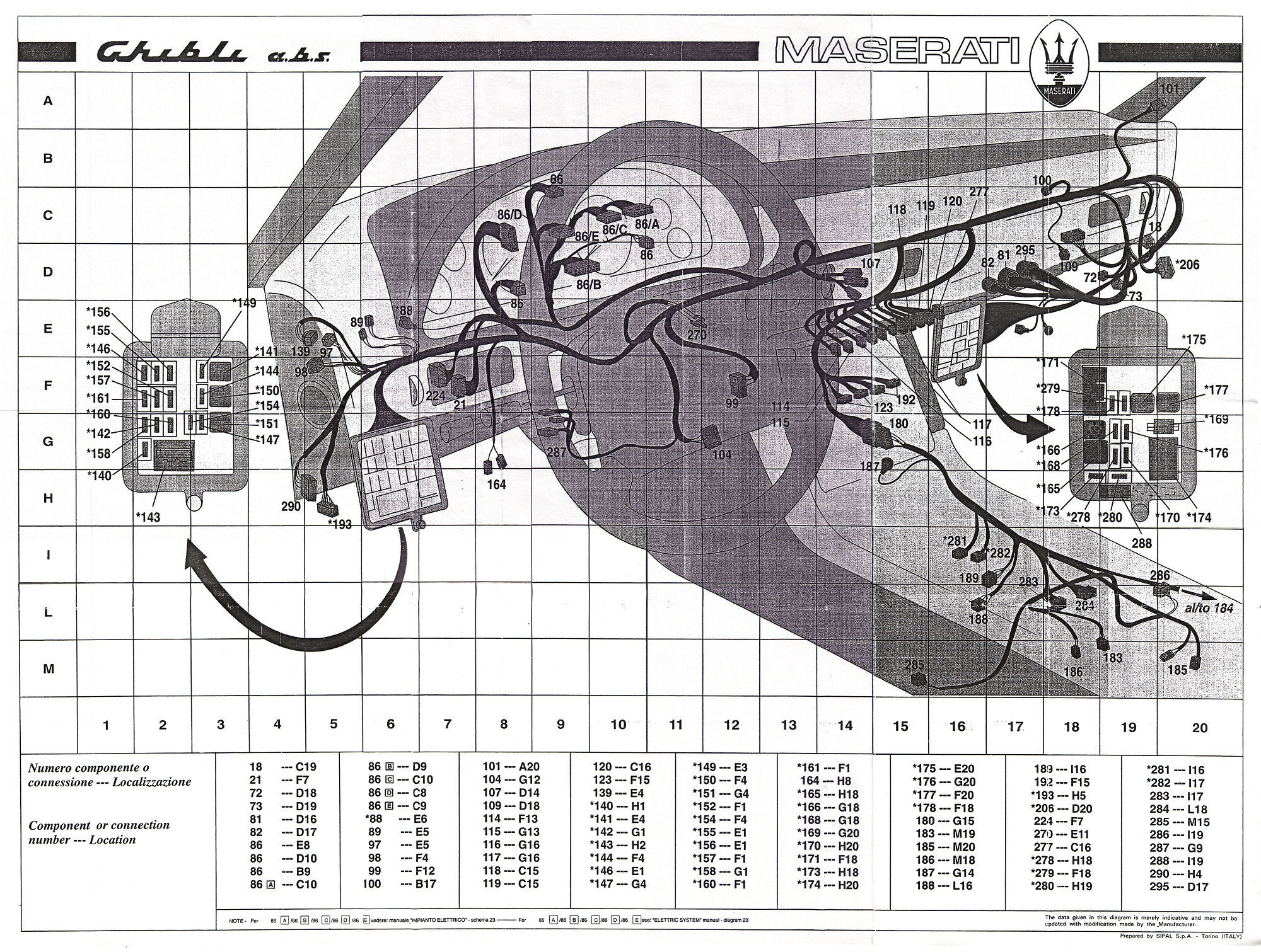
| Index to dashboard schematic electrical diagram | |||||
| Number | Component | Location | Number | Component | Location |
| 18 | Connection between dashboard cable & wheel antilock system cable (ABS) | C 19 | 140 | 30A fuse protecting steering column lock (in LH fusebox) | H 1 |
| 21 | Connection between dashboard cable and left engine bay cable | F 7 | 141 | Services relay (in LH fuse box) | E 4 |
| 72 | Electronic injection connector for cylinders 1,2,3 | D 18 | 142 | 30A fuse protecting car stop lights (in LH fuse box) | G 1 |
| 73 | Electronic injection connector for cylinders 4,5,6 | D 19 | 143 | Positive junction (in LH fuse box) | H 2 |
| 81 | Connection between dashboard cable and engine bay cable (7-way connector) | D 16 | 144 | 10A fuse protecting radio (in LH fuse box) | F 4 |
| 82 | Connection between dashboard cable and engine bay cable (10-way connector) | D 17 | 146 | 10A fuse protecting hazed lights and cluster (in LH fuse box) | E 1 |
| 86 | Instrument panel | D 10 | 147 | 7.5A fuse protecting rheostat adjusting cluster illumination (in LH fuse box) | G 4 |
| A | Left direction indicator light | C 10 | 149 | 30A fuse protecting steering column stalk unit (in LH fuse box) | E 3 |
| B | Heated rear window indicator | D 9 | 150 | Direction indicator/hazard lights flasher unit (in LH fuse box) | F 4 |
| C | Rear foglights indicator | C 10 | 151 | Relay controlling electric horns (in LH fuse box) | G 4 |
| D | Front foglights indicator | C 8 | 152 | 30A fuse protecting windscreen wiper control (in LH fuse box) | F 1 |
| E | Main beam headlights indicator | C 9 | 154 | 7.5A fuse protecting button lights (in LH fusebox) | F 4 |
| F | Dipped headlights/side-tail lights indicator | Not shown | 155 | 7.5A fuse protecting heated rear window (in LH fusebox) | E 1 |
| G | Side lights, tail lights, number-plate lights, stop lights faulty indicator | Not shown | 156 | 7.5A fuse protecting boot/fuel flap release device (in LH fusebox) | E 1 |
| H | Injection system faulty indicator | Not shown | 157 | 15A fuse protecting clock, radio memories and air conditioner (in LH fusebox) | F 1 |
| I | Wiring for electronic clutch indicator | Not shown | 158 | 30A fuse protecting hazard lights (in LH fusebox) | G 1 |
| J | Seatbelts not buckled indicator |
Not shown | 160 | 7.5A fuse protecting electric mirrors and left-hand door lights (in LH fusebox) | F 1 |
| K | Wheel antilock system faulty indicator (ABS) | Not shown | 161 | 30A fuse protecting electric horns (in LH fusebox) | F 1 |
| L | Brake linings worn/brake fluid level low indicator | Not shown | 164 | Car braking signalling switch | H 8 |
| M | Handbrake ON indicator | Not shown | 165 | 30A fuse protecting steering column stalk unit (in LH fuse box) | H 18 |
| N | Engine low oil level indicator | Not shown | 166 | Control unit with buzzer for seatbelts/lights ON (in RH fusebox) | G 18 |
| O | AIRBAG circuit faulty indicator | Not shown | 168 | 30A fuse protecting cigar lighter and door lock (in RH fusebox) | G 18 |
| P | Right direction indicator light | Not shown | 169 | Seat protection (in RH fuse box) | G 20 |
| Q | Cluster illumination lamps | Not shown | 170 | 30A fuse protecting front electric windows (in RH fusebox) | H 20 |
| R | Engine low oil pressure indicator | Not shown | 171 | Door lock control unit (in RH fusebox) | F 18 |
| S | Engine oil pressure gauge | Not shown | 172 | 7.5A fuse protecting ceiling lamps illuminating the inside of the car/right door lights (in RH fusebox) | Not shown |
| T | Engine coolant temperature gauge | Not shown | 173 | 7.5A fuse protecting suspension, ABS, vacuum pump, seat-belts buzzer and front inside lights (in RH fusebox) |
H 18 |
| U | Engine coolant temperature high indicator | Not shown | 174 | Positive junction (in RH fuse box) | H 20 |
| V | Speedometer | Not shown | 175 | Air conditioner control relay (in RH fuse box) | E 20 |
| W | Turbo overpressure pressure/vacuum meter | Not shown | 176 | 30A fuse protecting air conditioner (in RH fusebox) | G 20 |
| X | Rev counter | Not shown | 177 | Electric windows control relay (in RH fusebox) | F 20 |
| Y | Cluster illumination dimmer | Not shown | 178 | 7.5A fuse protecting oil level control unit (in RH fusebox) | F 18 |
| Z | Fuel level gauge | Not shown | 180 | Console connector | G 15 |
| AA | Fuel reserve indicator | Not shown | 183 | Handbrake ON signalling switch | M 19 |
| AB | Voltmeter | Not shown | 185 | Cigar lighter | M 20 |
| AC | Battery charge low indicator | Not shown | 186 | Seatbelts not buckled signalling switch | M 18 |
| AD | Electronic control unit for processing outside temperature switch and icy road surface indicator (*C/*F) |
Not shown | 187 | Console ground/earth | G 14 |
| 88 | Cabin left-hand ground/earth | E 6 | 188 | Automatic transmission illumination | L 16 |
| 89 | Wiring for buzzer | E 5 | A | For manual transmission versions | L 16 |
| 97 | 2-way connector for EKS wiring | E 5 | B | For automatic transmission versions | L 16 |
| 98 | 6-way connector for EKS wiring | F 4 | 189 | Switch for backup lights and automatic transmission start-up enable device | I 16 |
| 99 | Ignition switch | F 12 | A | For manual transmission versions | I 16 |
| 100 | Wiring for headlights diode | B 17 | B | For automatic transmission versions | I 16 |
| 101 | Connection between dashboard cable and ceiling lamp cable | A 20 | 192 | Wiring for car radio | F 15 |
| 104 | Steerine column stalk unit | G 12 | 193 | Left door connector (black) | H 5 |
| A | Windscreen wiper switch | G 12 | 206 | Right door connector (black) | D 20 |
| B | Windscreen washer button | G 12 | 224 | Right wiring connector (red) | F 7 |
| C | Control switch forside/tail lights, main/dipped headlights unit | G 12 | 270 | Wing mirrors fold-in control | E 11 |
| D | Direction indicators control switch | G 12 | 277 | Door open indicator | C 16 |
| E | Main beam headlights flasher button | G 12 | 278 | 10A fuse protecting right door light (in RH fuse box) | H 18 |
| F | Horn button | G 12 | 279 | 30A fuse protecting seats adjustment (in RH fuse box) | F 18 |
| G | Rheostat adjusting winscreen wiper intermittance | G 12 | 280 | 7.5A fuse protecting centre ceiling lamp (in RH fuse box) | H 19 |
| 107 | Analogue clock | D 14 | 281 | Left electric window button pad on console | I 16 |
| 109 | Control unit controlling electronically-adjusted suspension (KONI) | D 18 | 282 | Right electric window button pad on console | I 17 |
| 114 | Front fog lights switch | F 13 | 283 | Button pad controlling driver's seat back adjustment | I 17 |
| 115 | Rear fog lights switch | G 13 | 284 | Button pad controlling passenger's seat back adjustment | L 18 |
| 116 | Heated rear window switch | G 16 | 285 | Motor adjusting driver's seat back | M 15 |
| 117 | Hazard lights switch | G 16 | 286 | Motor adjusting passenger's seat back | I 19 |
| 118 | Clock illumination switch | C 15 | 287 | Parking lights switch | G 9 |
| 119 | Fuel flap release switch | C 15 | 288 | Rear fog lights circuit diodes | I 19 |
| 120 | Boot release switch | C 16 | 290 | Windscreen wiper timer | H 4 |
| 123 | Connection between dashboard cable and air conditioner cable (black) | F 15 | 295 | Connection between dashboard cable and engine bay cable (29- or 23-way connector depending on the car) |
D 17 |
| 139 | Car alarm connector | E 4 | |||
 |
||
|
To enter Enrico's Maserati Pages CLICK HERE! Copyright: Enrico's Maserati Pages - © 2000-2009. All rights reserved. |