| |
There has been a lot of bull written by Maserati in its brochures about how this system works.
Oil charged with metal particles, shock absorbers able to sense road condition and adjust themselves. Certainly a lot more, but now it's time to see how the system really works. |
| |
From the Maserati Quattroporte IV "Libro di Uso e Manutenzione" |
| |
I have described the internal workings of a Quattroporte IV adjustable shock absorber in my L'anatomie d'amortisseur ajutable de Maserati Quattroporte IV. It's in French but the photos are sufficient to enable one to understand the principles.
Note that the shock absorbers fitted to the 2.24v./4.24v./Ghibli II and Quattroporte IV are all built in the same way and can be inter-changed in the same car.
Actually the front and rear shocks are also inter-changeable.
The system only works if all four shock absorbers are functioning.
THE SYSTEM
The system contains:
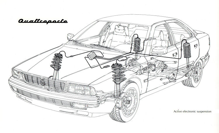
4 electronically adjustable shock absorbers
A computer
A control panel with a button and 5 LEDs (4 green and 1 red)
A wiring harness that is independent from the rest of the car (so the system can be fitted to any Biturbo
model with 5 bolt rims) |
| |
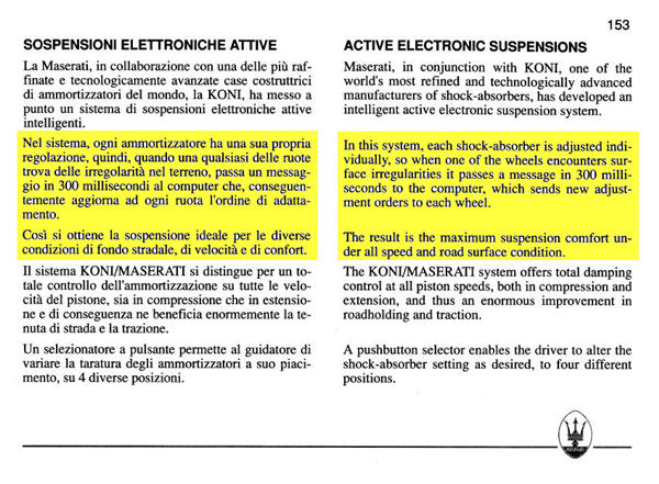
The Maserati Quattroporte IV "Active Electronic Suspension" System |
| |
Overall, the system is quite simple:
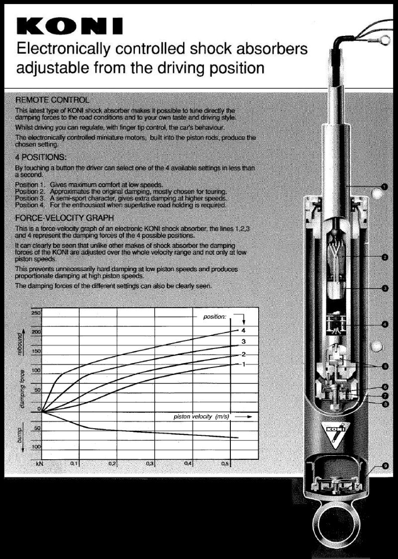
There are four suspension settings ranging from soft to stiff:
Position 1: Very soft, to provide maximum comfort at low speeds.
Position 2: Suitable for cruising speeds of up to 160 km/h.
Position 3: Ideal compromise between driveability, handling and comfort.
Position 4: Strictly for the driver used to stiff sports car suspension.
The driver selects the desired setting for the shock absorbers. The computer indicates that setting and changes the ride to the required setting. If a failure is detected, the system shuts down, and the red status LED is switched on. That's it. |
| |
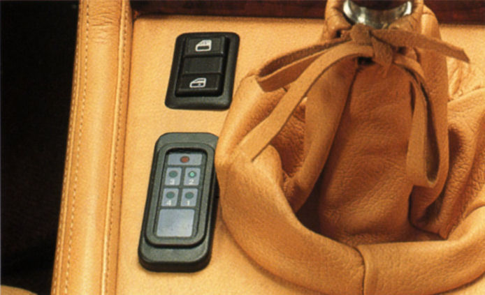
The shock absorber control panel with a button and 5 LEDs (4 green and 1 red) |
| |
There is NO magic system sensing road conditions. There is no real-time control except to follow the driver's instruction to adjust the required hardness.
The KONI shocks have slightly different lengths compared to standard units, but they are still inter-changable. |
| |
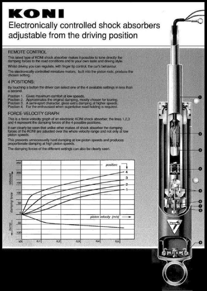
The Koni electronically controlled shock absorber |
| |
CONTROL PANEL
There are two versions of the control panel:
A 5 LED small board fixed close to the gear lever
5 LEDs on the dashboard and the button close to the gear lever
Both versions use the same computer.
The control panel contains circuits that sense the control button, show the chosen position on green LEDs and send the position 2-bit code to the computer. The panel is powered by the computer.
The status red LED is driven by the computer through a special wire.
The computer does not know whether control panel works as any combination of the 2-bit code that computer receives is valid.
SERVO-MOTORS
The pictures below show the servo-motor located in the shock. |
| |
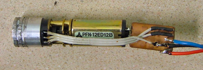
The servo-motor located inside the shock absorber |
| |
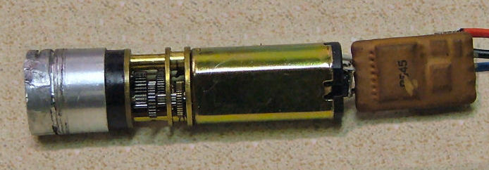
Reverse side of the servo-motor located inside the shock absorber |
| |
We see a motor, gear, position pot and electronics. It's a classic servo-control design. It's powered by a 12v supply. And it's controlled by a classic PWM pulse signal.
The computer sends a 5v pulse every 10ms. Pulses are 0.5/1/1.5/2 ms long for four positions.
One may use a standard RC model servo-controller to adjust shocks. However beware of noise on the line that may make servo positioning not precise.
COMPUTER
The internal components of the computer are as illustrated: |
| |
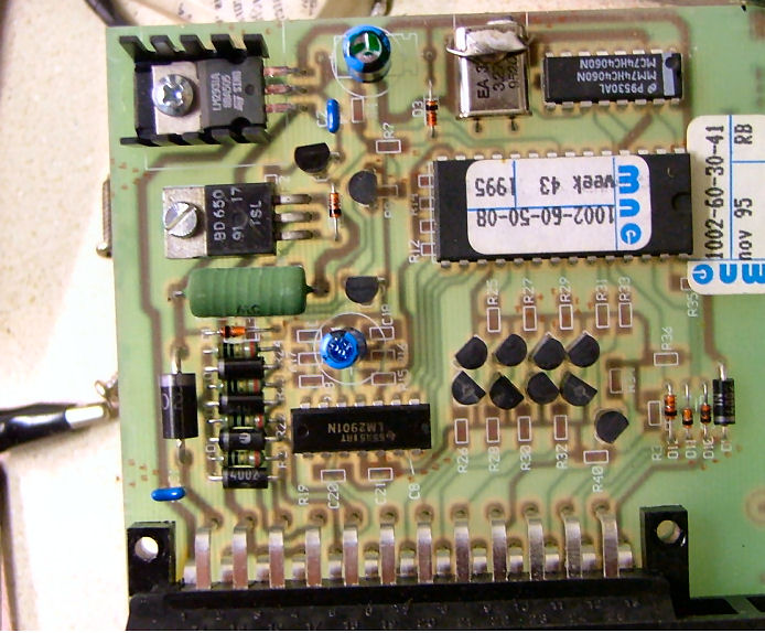
The internal components of the computer |
| |
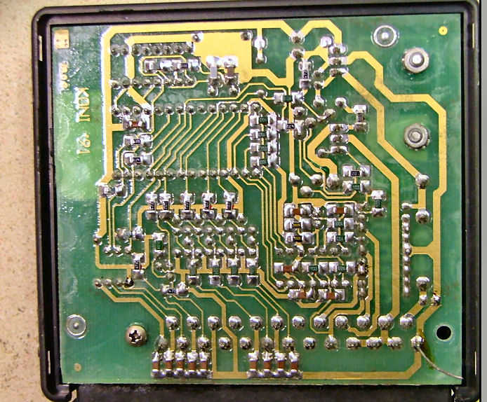
The internal components of the computer |
| |
We can see:
Microcontroller (MCU), PIC16C55-XTI/P (OTP ROM)
74HC4060 - oscillator for MCU
LM2931A - +5v power source
BD650 - p-n-p Darlington to supply 12v to shocks
LM2901 - OpAmps to sense shock consumption current
4 transistor pairs - to send signals to 4 shocks
9th n-p-n - to control the status/error LED
4 1N4002 - to supply ground to shocks
25 pin AMP Junior-Timer connector
Each time there is a change of the shock adjustment the MCU expects it to consume current during some amount of time. The OpAmp senses this current and sends a binary signal to the MCU if consumption is significant. This is how MCU knows that each shock works.
All shocks get the same control signal and in the same time.
When computer is powered up it first sends two different positions to all shocks. If the observed consumption is compliant to its expectations then it switched off the status LED and the system is ready.
If an abnormal behavior was observed then computer makes 4 attemps to set these two positions and then lights on the error LED.
If no control panel is connected then shocks are left in position 1 (softest).
Next picture shows the entire wiring harness |
| |
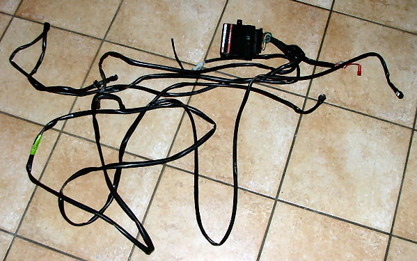
The entire electronically controlled adjustable suspension wiring harness |
| |
ERROR CODES
Even if MCU knows exactly which shocks have unexpected behavior it does not give us this information.
I observed two error codes:
Iif any shock is disconnected then the status LED stays on
If a failure on a shock was observed then the LED blinks (I could not reproduce that later)
DIAGNOSTIC MODE
The wiring harness contains a 1-pin red connector that should be near the control panel or the selection button. This connector is normally open.
If you close it (at any time) the system enters the diagnostic mode in which the computer cycles over the following steps:
Send one by one the 4 positions to the shocks (about every 2 seconds, from position 4 (hardest) to 1 (softest)
Shut down shocks and blink the red LED eight times
In this mode computer does not care about how many shocks are connected and whether they work.
If a shock is working you will hear its motor rotate.
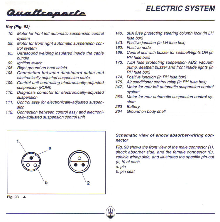
HARNESS WIRING PIN OUT
The shock connector pin out:
Pin 1 : +12v, red wire
Pin 2 : control signal, blue wire
Pin 3 : ground, black wire
I did not try to know where every shock is connected to the computer. So let's call them 1..4.
Shock 1 pins 2, 17, 21
Shock 2 pins 3, 8, 16
Shock 3 pins 4, 5, 7
Shock 4 pins 15, 18, 20
The computer 25-pin connector pin out: |
| |
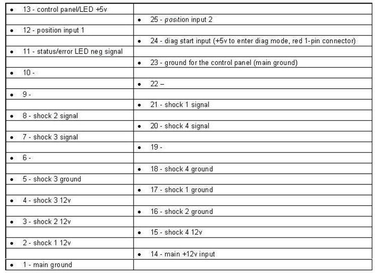
The computer 25-pin connector pin out |
| |
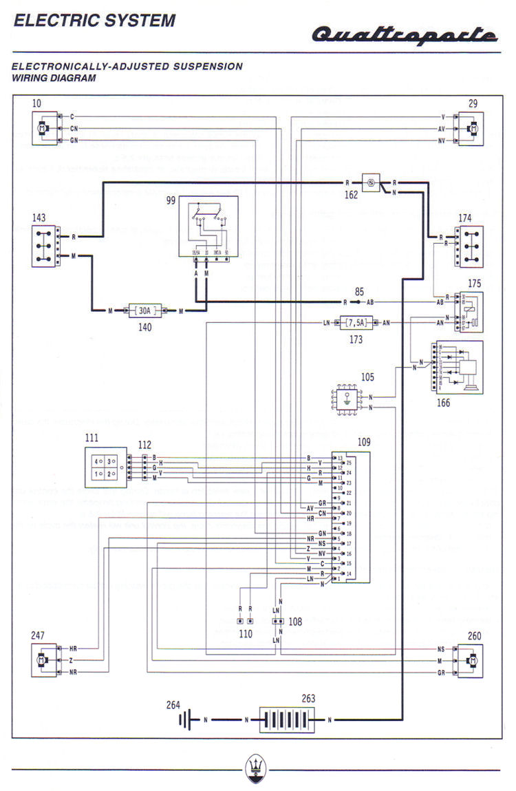
The Electronically Controlled Adjustable Suspension System Wiring Diagram |
| |
The Key to Components |
| |
Position inputs 1 and 2 receive a binary encoded number of the requested position from the control panel.
We get 00/01/10/11 combinations. I don't know which code is for which position.
The control panel can be replaced by two 2-position switches that close the inputs to the ground. The four combinations will encode the four adjustment positions.
SHOCK FAILURE
It's not surprising that after some amount of working hours the servo-motor will wear and die.
However there is another source of failures: the cable. The servo cable that links motor to the shock connector can be worn exactly where it enters the shock.
Below is a picture of the cable wires as I found them: |
| |
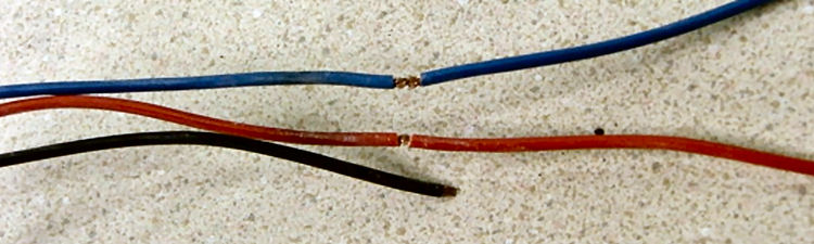
The damage to the wiring that is often the cause of a systems failure |
| |